
Posted At: Tem 25, 2023 - 453 Views
Multi-antenna techniques, often referred to as advanced antenna systems (AAS), employ beamforming and multiple-input multiple-output (MIMO) technologies. Eyeing large-scale deployments in the existing 4G and the future 5G networks, these phased-array antennas are being deployed both in sub-6-GHz and millimeter-wave (mmWave) frequency bands to boost wireless capacity. How does it work? A phased-array antenna formed by an array of smaller antenna elements can steer a beam in a chosen direction while using the varying phases and amplitudes of the signal. These antenna arrays form narrow beams, which are dynamically steered in the desired direction, a concept otherwise known as beam steering.
In the sub-6-GHz frequency band, 5G designs apply several transmit and receive antenna elements in order to serve multiple users with parallel data streams. These massive-MIMO systems employ a high number of transmitting and receive antenna elements to facilitate sophisticated amplitude- and phase-control mechanisms. The design of these antenna arrays in multi-user MIMO systems is challenging enough in the 6-GHz band. However, in mmWave communication designs, where high path loss attenuation mandates high antenna gains, 5G designers have the daunting task of overcoming the signal-propagation issues. That’s why mmWave antennas must deliver highly directional antennas with higher gain while using techniques like dynamic beamforming.
It all begins with passive antenna arrays being measured for signal phase and amplitude both in lab and production environments. Then, they can be integrated into active beamforming antenna systems for characterization of parameters such as effective isotropic radiated power (EiRP), error vector magnitude (EVM), total isotropic sensitivity (TIS), and total radiated power (TRP).
Active antenna arrays—which integrate antennas, power amplifiers (PAs) and phase shifters in a single PCB-mountable package—facilitate active beamsteering switched on and off dynamically within milliseconds in a real-life mobile environment. The challenges confronting AAS include phase-shifter tolerances, thermal effects of the PA, and frequency drifts between modules. That can impact the desired beam patters and thus calls for careful a characterization of beam patterns and related parameters such as beam width, sidelobe levels, null depths, etc.
Antenna-Array Test challenges
The 5G base stations are going to employ hundreds of antennas for massive-MIMO streams. Therefore, unlike the conventional test systems, the new measurement solutions must offer higher adaptivity and steerability. That will allow them to efficiently calculate antenna radiation patterns and thus gauge time-varying traffic and multi-path radio propagation conditions rapidly (Fig. 1).
Fig. 1. Shown is a simulated linear array antenna radiation pattern with four antenna elements operating in the 28-GHz band at a spacing of 16 mm.

To start, in order to accommodate the new 5G testing needs for antenna arrays, there’s a need for measurement techniques that don’t treat antenna arrays merely as a single piece of equipment. In other words, they should be able to perform system-level tests for antenna modules, also known as antenna-in-packages (AiPs). So far, test engineers have been simulating antenna effects using manual and iterative processes that can prove awkward and time-consuming in highly complex 5G design realms like antenna-array measurements. The use of traditional methods for simulation of multiple antenna feeds also adds to cost and limits the quality of test procedures.
Moreover, while discrete components like phase shifters, switches, and amplifiers can be tested in conducted environments, phased-array antennas are usually integrated into a single hardware unit. So, in an AAS, typically comprising highly nonlinear PA, feed network and antenna elements, the traditional RF output ports are no longer accessible.
In addition, fiber interfaces are replacing the traditional RF input ports for digital I/Q data. Not surprisingly, therefore, the highly integrated antenna-array systems usually have no place to probe and no place to put connectors. Thus, enter over-the-air (OTA) solutions to handle the new kinds of 5G testing challenges.
OTA-Based Beamforming Tests
First, it’s important to note that the OTA measurements on massive-MIMO active antenna systems operate in cellular frequencies below 6 GHz as well as in the mmWave frequency ranges, and they both demand sophisticated calculation methods for radiation patterns.
However, in mmWave communications, which demands highly directional antennas with higher gain, antenna elements can be spaced more tightly, leading to extremely compact arrays. Such a high level of antenna integration makes the use of traditional RF connectors between the radio circuit and the antenna highly impractical.
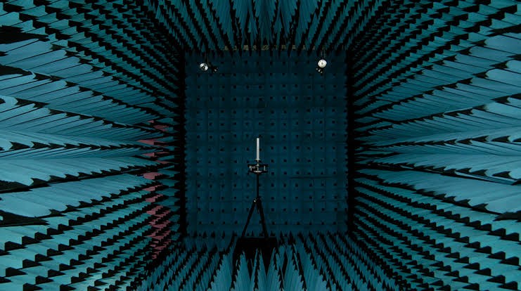
Fig. 2. OTA testing is becoming a viable alternative to test instruments using cables, especially in 5G antenna arrays integrated into a package, which prohibits antenna elements’ direct connection to cables in a conducted environment.

The wave propagation in lower frequencies significantly differs from the mmWave bands because the path loss of lower frequencies is smaller than higher frequencies. The risk of high propagation loss and fading at mmWave frequencies also leads to multi-element antenna arrays that are highly integrated. Ultimately, the increased frequencies, new package technologies, and greater antenna counts make the OTA test setups imperative for 5G antenna designs (Fig. 2). The fact that OTA solutions enable engineers to test antenna arrays as a system instead of a set of individual elements operating in parallel also enhances efficiency and reduces complexity.
The carefully calibrated OTA test setups facilitate fast and accurate signal characterization, verification measurements, and functional testing of 5G antenna arrays. However, it’s important to note that antenna arrays employ both conducted and OTA test methods to characterize MIMO and beamforming technologies.
Network Analyzers and OTA Test Chambers
Take, for instance, beamforming ICs that support four or more antenna elements from one input signal. They require the simultaneous assessment of all ports for absolute and relative phase-level measurements. Here, a multiport vector network analyzer (VNA) can ensure the fast and direct evaluation of all individual channels by establishing a parallel connection to all RF ports of the beamforming IC.
The VNA can characterize each functional block, from switches to amplifiers, inside the beamforming IC while it monitors all antenna connections under varying conditions (Fig. 3). Another standard task of VNAs is checking the impedance matching of the beamformer IC toward the antenna.
Fig. 3. This is how a vector network analyzer enables multiple antenna elements to be tested in a phased-array system, in order to fully characterize and calibrate 5G wideband signals.

Testing Path to 5G Antennas
The entire 5G design landscape is filled with complex engineering challenges, including the fast and accurate antenna characterization, a prerequisite in 5G beamforming architectures. However, the prototypes of 5G user equipment (EU) and radio base stations are already being designed with multi-element antenna arrays that are driven by adaptive beamforming and beam-steering technologies.
The article has shown that new test instruments and methods are being developed to efficiently characterize these antenna arrays in both conducted and OTA environments. It also shows how test-equipment suppliers and engineers are confronting the challenges posed by advanced antenna systems that are a driving force behind the rapidly shaping 5G MIMO and beamforming architectures.